Innovative Manufacturer of Honeycomb and MI Heating Products
Innovative Manufacturer of Honeycomb and MI Heating Products
Product Details:
Payment & Shipping Terms:
|
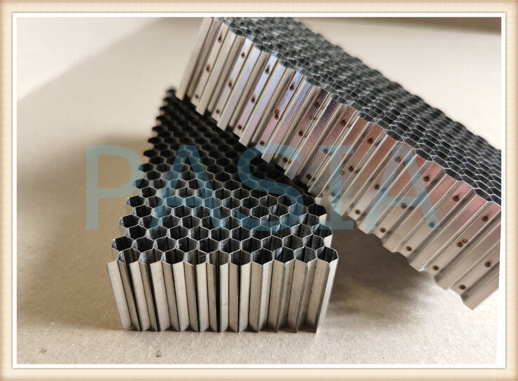
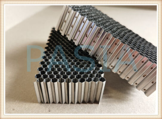
| Material: | Stainless Steel | Bonding: | Spot Welding Or Laser |
|---|---|---|---|
| Material Thickness: | 0.05 | Cell Side Length: | 3 |
| Height: | 3-250 Mm | Applications: | Filtering, Sealing, Shielding, Separating, Guiding And Platform |
| Grade: | SS304,SS316L |
High Efficiency Welded Honeycomb Air Flow Seal Replacing Traditional Labyrinth Seal
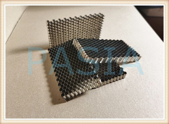
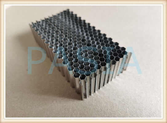
The High-Efficiency Honeycomb Air Seal is a next-generation gas-path sealing solution engineered to directly replace conventional labyrinth seals in aero-engines, gas turbines, steam turbines, and compressors. Manufactured from nickel-based superalloy foil (such as Hastelloy X / GH3536) precision-formed into a hexagonal honeycomb cellular structure and vacuum-brazed onto a support ring, this seal delivers superior leakage control, enhanced rotordynamic stability, and improved overall turbine efficiency.
Unlike labyrinth seals that rely on complex tooth geometries to create flow resistance, the honeycomb seal leverages its unique cellular structure to kill swirl velocity and dissipate flow kinetic energy, achieving fundamentally better sealing performance with greater operational robustness.
2. Why Replace Labyrinth Seals?
Labyrinth seals have been the industry standard for decades due to their simplicity and reliability. However, they come with inherent limitations:
Limitation Consequence
High leakage rates Reduced engine efficiency, increased fuel consumption
Sensitivity to eccentricity Performance degrades significantly with installation errors
Poor damping characteristics Rotordynamic instability risks
Temperature limitations Prone to failure at high compressor discharge temperatures
Blade tip clearance constraints Cannot accommodate blade rub without damage
The honeycomb air seal directly addresses each of these limitations, offering a drop-in replacement that delivers immediate and measurable performance improvements.
3. Core Advantages Over Labyrinth Seals
3.1 Superior Leakage Reduction
Up to 30–70% less leakage compared to conventional labyrinth seals.
· For long seals (L > 50 mm), honeycomb seals leak about one-third less than a standard labyrinth
· Labyrinth seals with partial honeycomb lands achieve up to 39.4% reduction in discharge coefficient
· Mixed honeycomb seal designs show performance improvements of up to 19% (less leakage) compared to uniform honeycomb seals
· Straight-tooth honeycomb geometry reduces leakage by ~11% ; inclined-tooth arrangements increase this to 21.5%
3.2 Improved Turbine Efficiency
· Replacement of labyrinth seals with honeycomb seals yields ~30% leakage reduction and 0.6% stage efficiency improvement
· Radial gaps can be decreased from 1.5 mm to 0.5 mm, increasing turbine cylinder efficiency by approximately 1% at the initial stage
· Corresponding gain in turbine set power output
3.3 Superior Rotordynamic Stability
· Honeycomb seals have much higher values of effective damping than labyrinth seals
· Cross-coupled stiffness coefficients are comparable to labyrinth seals, while direct damping is significantly larger
· The honeycomb seal is the least sensitive to eccentricity among all seal types
· Honeycomb structure kills swirl velocity development, reducing destabilizing forces
3.4 Abradable Blade Protection
The honeycomb structure serves as a sacrificial abradable layer:
· During the first engine start, blade tips gently cut into the honeycomb, wearing in-situ to form a perfect gas-tight seal
· Protects expensive ceramic-tipped turbine blades from damage
· Enables tighter radial clearances without risk of catastrophic blade-casing contact
· Linear wear ratio of sealing material to blade is 10:1
3.5 Higher Temperature Capability
· Honeycomb seals are capable of sustaining higher temperatures
· Conventional labyrinth seals are prone to failure at high compressor discharge temperatures
· Nickel-based superalloy construction (Hastelloy X / GH3536) provides reliable service up to 900°C long-term (1080°C short-term)
3.6 Manufacturing Efficiency
· Labor input to fabricate honeycomb seals is six to eight times smaller than that for labyrinth seals with honeycomb inserts
· Rectangular-cellular seal designs can yield an additional 0.5–1.0% efficiency improvement
Specifications
| Cell Size (mm) | 25.0 | 16.0 | 12.7 | 10.0 | 6.4 | 5.6 | 4.8 | 3.2 | 1.6 | 0.8 |
| Height Range (mm) | 50-450 | 50-450 | 50-150 | 50-150 | 5-100 | 5-90 | 5-60 | 5-60 | 3-30 | 3-25 |
| Foil Thickness (mm) | 0.20 | 0.20 | 0.20 | 0.20 | 0.20 | 0.20 | 0.20 | 0.20 | 0.076 | 0.05 |
| Cubic Density (kg/m3) | 165 | 256 | 320 | 403 | 616 | 699 | 806 | 1164 | 909 | 1164 |
| Materials | SS304, SS316 or SS316L | |||||||||
| Welding | Spot Welding with one area five spots or laser welding | |||||||||
| Shapes | Customized shape available not limited to ring, plate, loop etc | |||||||||
Properties
Welded honeycomb core, no matter what material is, such as aluminum, stainless steel, steel, titanium etc, possesses better mechanical properties against regularly produced glued honeycomb core. So it performs significantly better again the common honeycomb bonded by adhesive on strength, modulus, corrosion resistance, dimensional stability etc. However, generally, these critical performance variables should be evaluated: material, airflow and attenuation.
1. Material Composition
Stainless steel grade should be considered according to the real application. Custom materials other than stainless steel are available upon request. Here are the parameters need to be evaluated:
Durability
Material type and grade is the first aspect to be evaluated then plating, discussed in depth later, can improve durability.
Weight
Material, structure and thickness of the material can affect the total part weight.
2. Corrosion resistance
Typically brass and stainless steel should be used in slashing environments. Plating or nonconductive surface coatings can improve corrosion resistance for all honeycomb types.
3. Shielding Performance
Different honeycomb core material offerings have different electrical performance, due to both inherent base material properties as well as the differing manufacturing processes used during honeycomb forming. Therefore, different EMI shielding performance may be realized. Shielding performance for different materials is ranked as brass, aluminum, steel and stainless steel. Plating can improve honeycomb shielding.
Specific attenuation requirements can be met through either plated or unplated alloys. Plating adds cost to the final product vent. Plating process for improving shielding is ranked as nickel, tin, tin-lead and zinc.
4. Airflow & Attenuation
Airflow and attenuation are inversely proportional. Infinitely large honeycomb cells result in infinitely small attenuation (and vice versa). Typically, as a design baseline, airflow performance requirements are calculated to meet thermal performance needs for the assembly that the vent is to be installed onto. Once airflow is determined, attenuation and other requirements can be evaluated. Standard cell sizes for honeycomb are 1/16", 1/8" and 1/4", with 1/8" being most common. Standard thicknesses are 1/4," 1/2" and 1," with 1/4" being most common.
Application
• air, water and gas flow straighteners and filters
• EMI/RF Shielding: scientific instruments, sensitive facilities, and hardening.
• tables for water jets
• light separators
• structural pieces in electronic cabinetry, aircraft, thrust reversers, exhaust nozzles
• aircraft engine honeycomb seals and power generation turbine seals