Innovative Manufacturer of Honeycomb and MI Heating Products
Innovative Manufacturer of Honeycomb and MI Heating Products
Product Details:
Payment & Shipping Terms:
|
| Process: | Vacuum Brazed | Material: | Haynes 214 |
|---|---|---|---|
| Industry: | Turbine | Usage: | Seal |
| Method: | Brazing | Grade: | 214 |
| Advantage: | Very Low Cross Coupling | Application: | Aircraft Engine Part |
Vacuum Brazed Nickel Superalloy Honeycomb Seal with Full Traceability
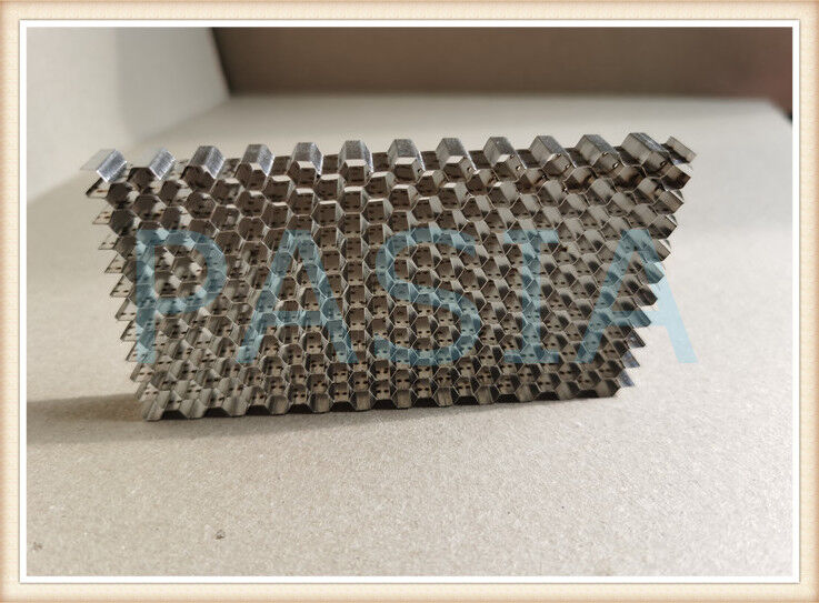
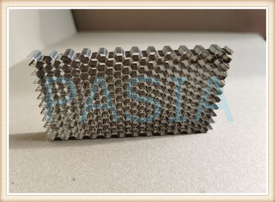
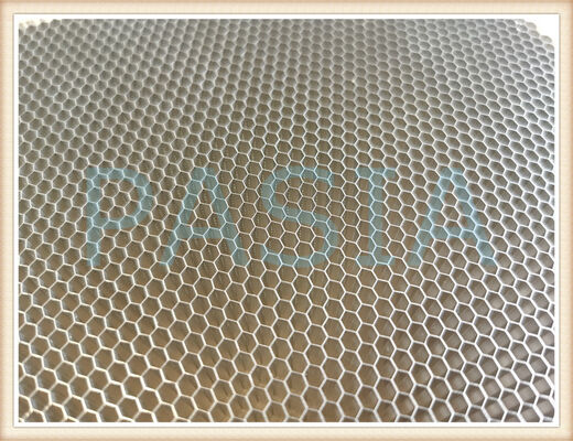
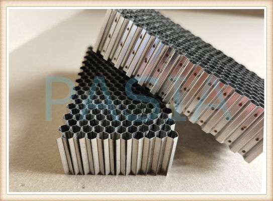
The Vacuum Brazed Nickel Superalloy Honeycomb Seal is a critical gas-path sealing component mounted in the annular groove of aero-engine casings, closely surrounding the rotating blade tips. The product is precision-formed from 0.05–0.1mm thick nickel-based superalloy foil into a regular hexagonal honeycomb structure, with the honeycomb core securely joined to the support ring via vacuum brazing.
Integrating nickel-based superalloy materials, precision vacuum brazing technology, and full-process quality traceability, this product is engineered for extreme aero-engine operating conditions and serves as a key enabler for improving engine efficiency and reducing fuel consumption.
2. Working Principle & Technical Features
2.1 Honeycomb Sealing Principle
The honeycomb seal features hexagonal cells ranging from 0.8 mm to 3.0 mm in diameter, with a maximum cell depth of 13 mm. During engine operation, the rotating blade tips, driven by centrifugal force, gently cut into the honeycomb structure, forming an optimal radial clearance fit. This "active wear" design allows the honeycomb core to function as a sacrificial abradable layer, protecting blades from dangerous contact with the rigid casing while minimizing gas-path leakage to the greatest extent.
2.2 Performance Comparison
Parameter Traditional Labyrinth Seal This Product
Gas-path leakage loss Baseline 50‑70% reduction
Operating temperature Limited Turbine-stage capable
Blade protection None Abradable honeycomb core
Process traceability Limited Full-chain traceable
3. Core Advantages
3.1 Nickel-Based Superalloy Material System
The honeycomb core is manufactured from GH536 (Hastelloy X) nickel-based superalloy, which exhibits excellent structural stability and oxidation resistance under combustor-grade high-temperature gases and thermal cycling conditions. Support ring (casing) materials can be selected from GH4169, GH907, GH600, or stainless steel depending on service conditions. This nickel-based material system ensures reliable performance in environments exceeding 900°C.
3.2 Vacuum Brazing Process
Vacuum brazing is the core manufacturing process for this product. Nickel-based brazing alloys (such as BNi‑2, BNi‑4, and BNi‑5) are used to join the honeycomb core to the support ring in a vacuum furnace.
Critical Process Controls:
Parameter Control Range
Brazing temperature 1030‑1180°C (depending on brazing alloy)
Soaking time Strictly controlled at 6‑15 minutes
Brazing filler amount Approximately 2× the volume required to fill the joint
Vacuum level Ensures oxidation-free, optimal wettability
Proprietary stepwise cooling control effectively prevents distortion of the honeycomb assembly during the brazing thermal cycle, ensuring dimensional stability. Vacuum brazed joint strength reaches approximately 50% of the base metal, meeting the stringent mechanical property requirements of aero-engines.
3.3 Full-Process Traceability
In the aero-engine industry, every single component's quality is a matter of flight safety. This product features an end-to-end traceability system:
Traceability Stage Data Captured Customer Value
Raw material Foil grade, batch, physical properties Source control
Honeycomb forming Stamping parameters, cell size, wall thickness Geometric accuracy guarantee
Assembly & tack welding Positioning parameters, assembly clearance Accurate alignment
Vacuum brazing Temperature profile, vacuum level, soak time Thermal cycle control verified
Non-destructive testing Fluorescent penetrant, X-ray records Zero defects policy
Final inspection Roundness, flatness, PCD hole diameter Right-first-time delivery
Each product carries a unique traceability code, allowing customers to retrieve all manufacturing and inspection data instantly — every part traceable, every step accountable.
4. Applications
4.1 Typical Installation Locations
· Compressor stator honeycomb seal segments
· Combustor front seal ring assemblies
· Turbine outer shroud honeycomb arcs
· Low‑pressure turbine rotor honeycomb assemblies
Engineered for Precision – Technical Specifications
Our honeycomb seal product line supports the following flexible specifications:
| Parameter | Specification Range |
| Material Options | Stainless Steel, Haynes 214, Hastelloy X, High-Temperature Alloy, Carbon Steel |
| Honeycomb Cell Size | 0.8 mm – 5.6 mm (0.8 mm, 1.6 mm, 2.0 mm, 3.2 mm, 4.2 mm, 5.6 mm, etc.) |
| Cell Wall Thickness | 0.08mm, 0.1mm, 0.13 mm, 0.15 mm, 0.2 mm (customizable) |
| Product Forms | Rings, Segments, Strips, Rectangular Sheets etc |
| Manufacturing Processes | Automatic Laser Welding, Vacuum Brazing etc |
Advantages
| 1 | Very low cross coupling |
| 2 | Higher direct damping that labyrinth seals |
| 3 | More forgiving than labyrinth seals in the event of a rotor-stator rub |
| 4 | Variety of materials available to serve a wide range of applications |
| 5 | Capable of sustaining higher temperatures than conventional labyrinth seals |